BPMN and DMN Notations
This page describes the graphical notations used for modeling business processes in the system: BPMN 2.0 — for describing sequential processes, and DMN 1.3 — for modeling decision rules. For each notation, the available elements and their purpose are listed.
2.4.1. BPMN Notation Overview
Using BPMN 2.0 components, you can easily model business processes by creating clear and understandable diagrams that serve as the foundation for their automation. BPMN acts as an intermediate link between the formalization/visualization and implementation of business processes, helping you better understand and manage your processes. Using the BPMN notation, you can use a variety of graphical elements to build business process diagrams.
BPMN diagrams contain the following main elements:
- Roles or responsibility zones: Pool/Lanes — elements used to display roles or responsibility zones in a business process.
- Control flow objects:
- Events — what must happen, for example, signing a contract or talking to a client.
- Actions — what must be done, for example, sending an email or retrieving data from an entity.
- Gateways — elements used to control the process flow based on certain conditions or events. They define how the process branches or merges at decision points.
- Connecting objects: Flows — a sequence of actions represented by an arrow. The flow element shows the sequence of actions in a business process.
- Artifacts:
- Annotations — objects used for additional description and supplementation of business processes. They help make models more understandable, detailed, and informative.
- Groups — objects used for the logical grouping of business process elements without affecting its execution.
- Data — objects that represent information used or created in the process.
2.4.1.1. Pool/Lane
Using the Pool and Lane elements, you can display the interaction of process participants during its execution.
- Pool — a collection of all process operations and the people responsible for their execution. It serves to define the boundaries of the process, giving you a clear picture of all stages and responsible participants.
- Lane is used to display specific performers or roles in the process. Within one pool, there can be multiple lanes, which helps you show in detail who is responsible for what at each stage of the process.
Thus, using Pools and Lanes, you can clearly and visually organize and show the interaction and responsibility of business process participants. Each lane contains the actions performed by a single executor.

2.4.1.2. Actions
An Action in a business process means a unit of work performed during its execution. Actions can be simple (tasks) or complex (subprocesses).
BPMN provides the following graphical notations for the main action types:
- Abstract Task
- Receive Message Task
- User Task
- Business Rule Task
- Service Task
- Script Task
- Call Activity (Process Reference)
- Subprocess
- Collapsed
- Expanded
- Event Subprocess
Abstract Task is used to denote a simple action or operation that has no further decomposition within the current business process.

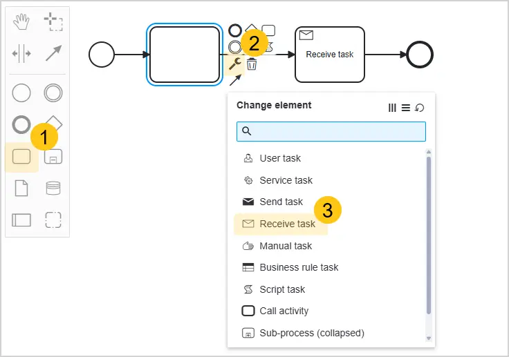
Receive Task is used to represent a process step that waits to receive a message with a specific code.
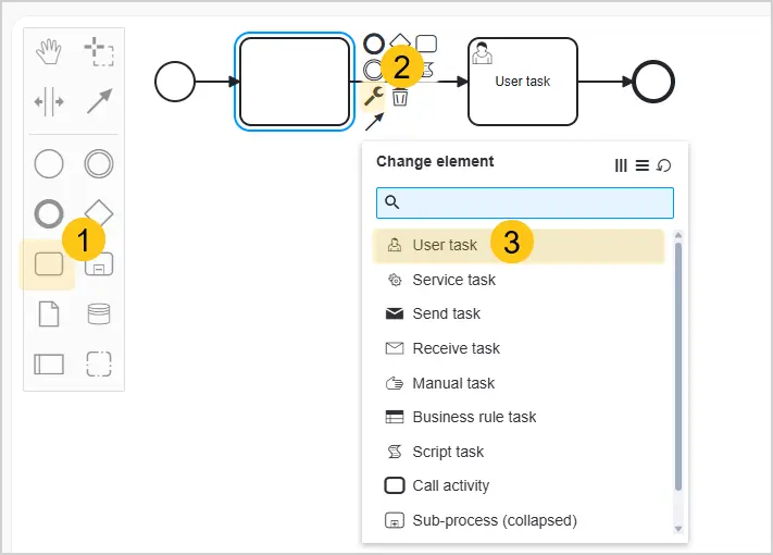
User Task is used to represent a task performed by a person.
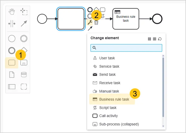
Business Rule Task is used to invoke business rules (DMN diagrams).
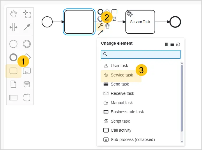
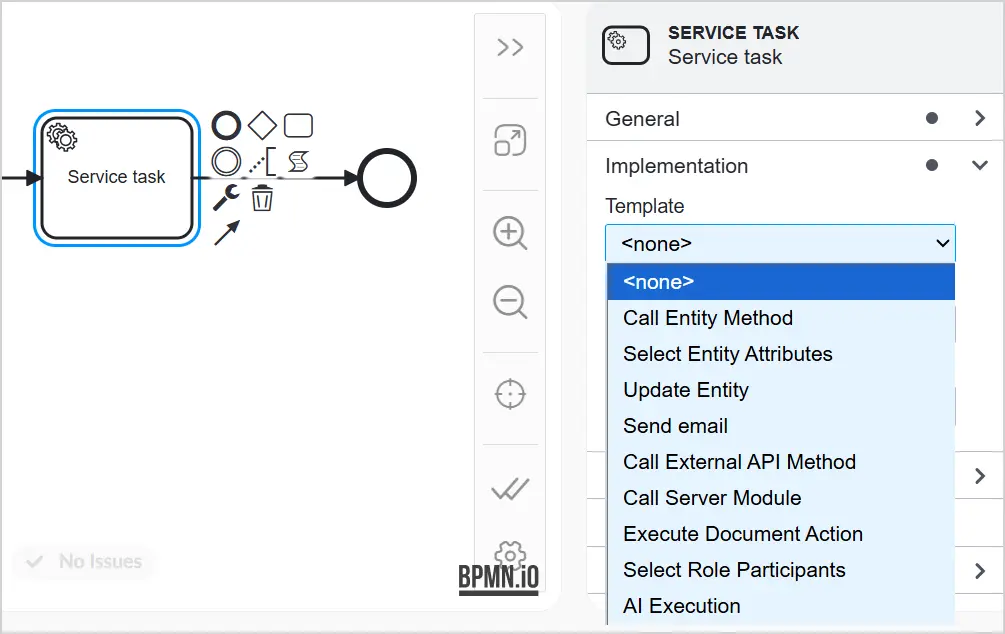
Service Task is used to invoke methods, retrieve data from entities, update objects, or send emails.
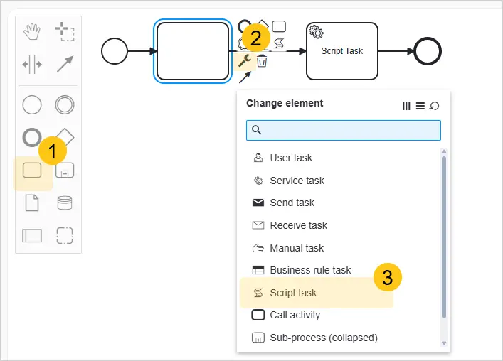
Script Task is used to represent a process step at which a script is automatically executed upon reaching it.
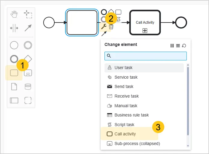
Call Activity (Process Reference) is used to denote a reference to one of the processes.
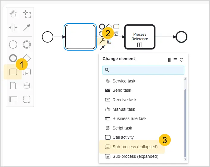
Subprocess is used to represent a complex process included within the current process. A subprocess can be:
-
Collapsed: the diagram does not display the details of the subprocess.
-
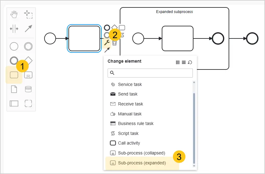
Expanded: the diagram displays the details of the subprocess.
Event Subprocess — a subprocess that is triggered by an event (for example, a message or a timer) and can fire at any point during the process execution.
2.4.1.3. Events
An Event is one of the main elements of BPMN and describes what must happen (as opposed to a task, which describes what must be done).
Example: An event could be the signing of a contract or a conversation with a client.
Graphical event elements in BPMN are classified by two criteria:
- Depending on the position of the event in the process diagram (see Event Position in the Process Diagram)
- By event type (see Main Event Types)
2.4.1.3.1. Event Position in the Process Diagram:
-
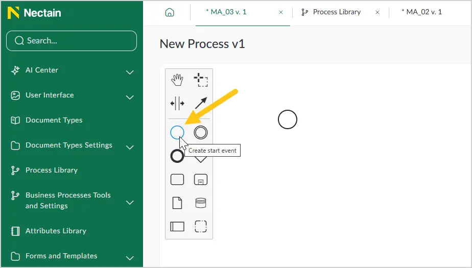
Start Event initiates the business process.
-
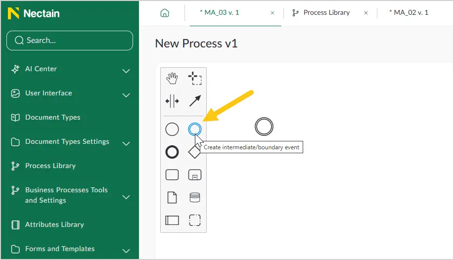
Intermediate Event
-
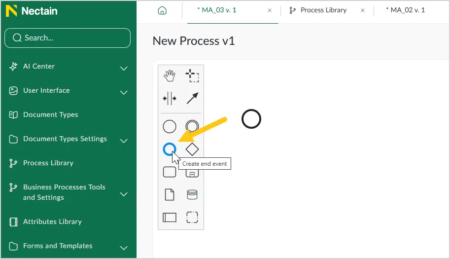
End Event terminates the business process.
2.4.1.3.2. Main Event Types
-
Simple Events — untyped events, most commonly used to indicate the start or end of a process.

-
Message Events represent the sending and receiving of messages during process execution.

-
Timer Events model events that occur regularly over time. They also allow modeling specific points in time, periods, and timeouts.

-
Escalation Events transfer the review of a task to a higher level of the organizational hierarchy.

-
Conditional Events allow business rules to be integrated into a process.

-
Error Events allow modeling the generation and handling of errors in a process. Errors can have different types.
 Note:
Note:To create a boundary error event:
-
From the elements panel, drag the task icon 1 onto the canvas 2.
-
From the elements panel, drag the generating event icon 1 to the bottom-left corner of the task on the canvas 2.

-
Change the type of the added event to Boundary Error Event.
-
-
Link Events are used for cross-page connections. A pair of corresponding link events is equivalent to a control flow.

-
Compensation Events initiate compensation or perform compensation actions.

-
Signal Events broadcast and receive signals across multiple processes. A single signal can be handled by multiple recipients. Thus, signal events allow implementing broadcast message distribution.

-
Terminate Events cause the immediate termination of the entire business process (across the whole diagram).

2.4.1.3.3. Change the Type of an Added Event
-
In the elements menu, select the required event position (Start, Intermediate, or End).
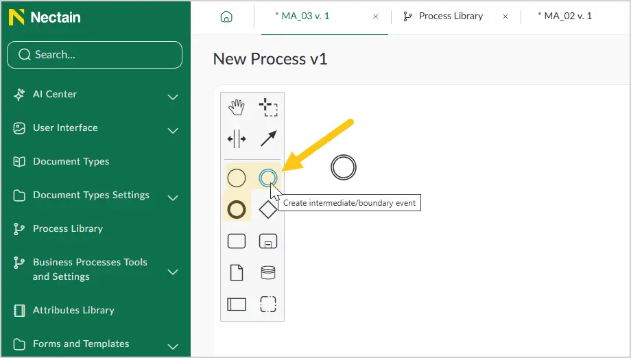
-
Click on the added event, then in the context menu, select the icon.
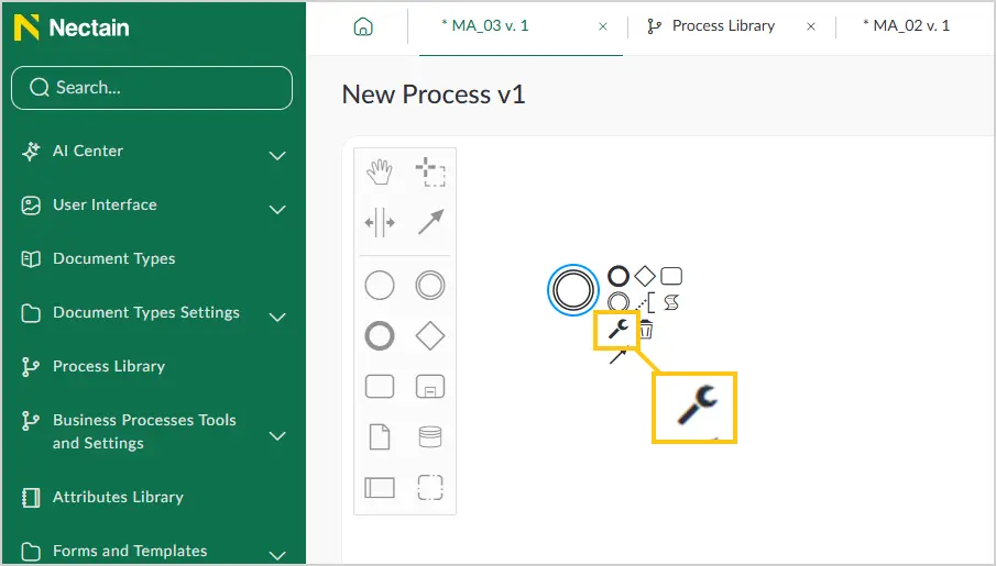
-
In the Change element type list, select the required event type. (See Main Event Types).
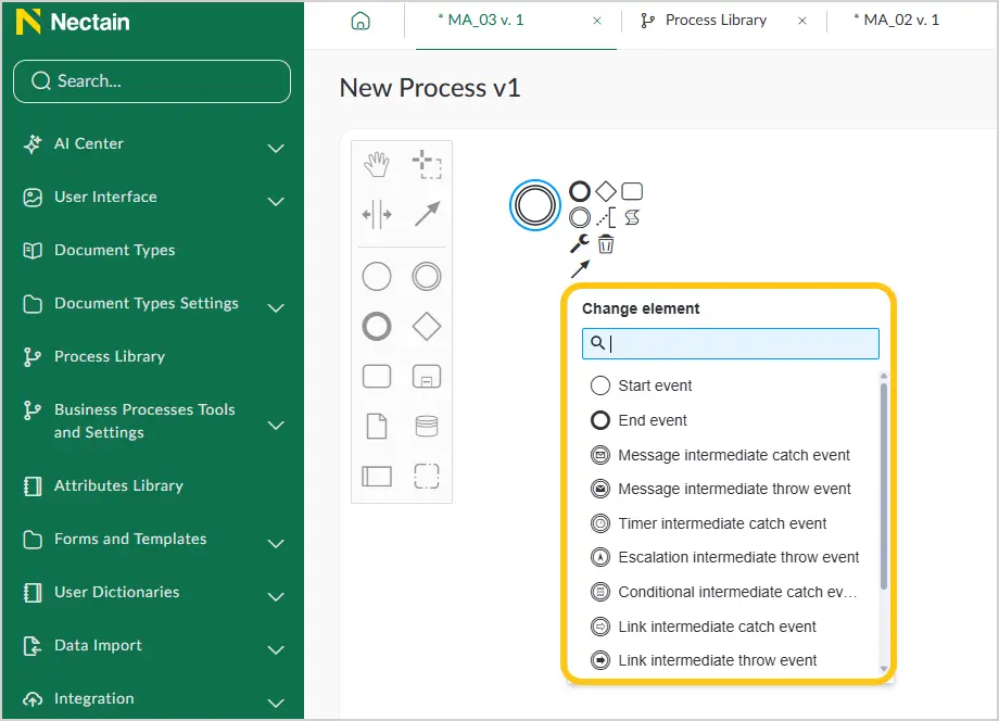
2.4.1.4. Gateways
Gateways are a modeling element used to control the process flow based on certain conditions or events. Gateways define how the process branches or merges at decision points. They help manage process complexity, enabling more flexible and clear business process modeling. An Gateway can be thought of as a gateway that either lets the flow through or not.
2.4.1.4.1. Add a Gateway
-
Switch to business process creation mode.
-
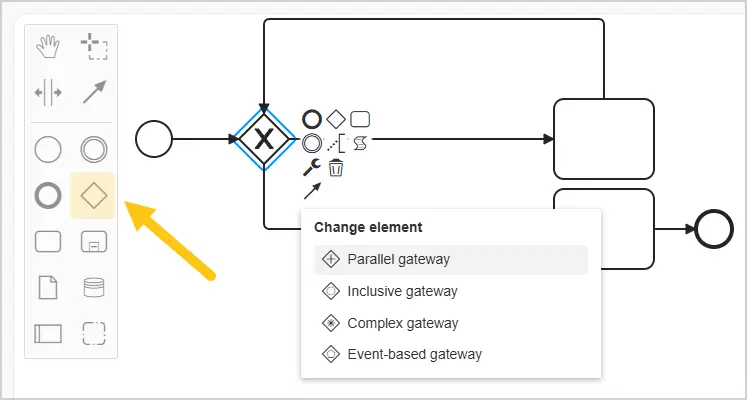
In the elements menu, select the icon, then click the location in the form where you want to insert the gateway.
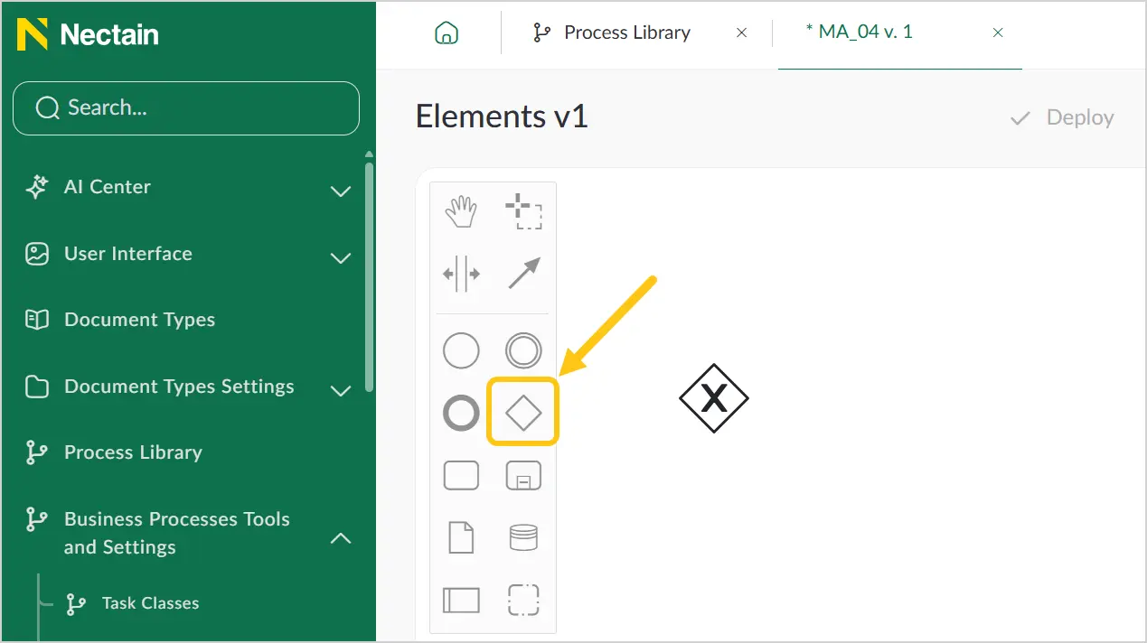
2.4.1.4.2. Change the Gateway Type
-
Add a gateway to the business process creation form (see Add a Gateway).
-
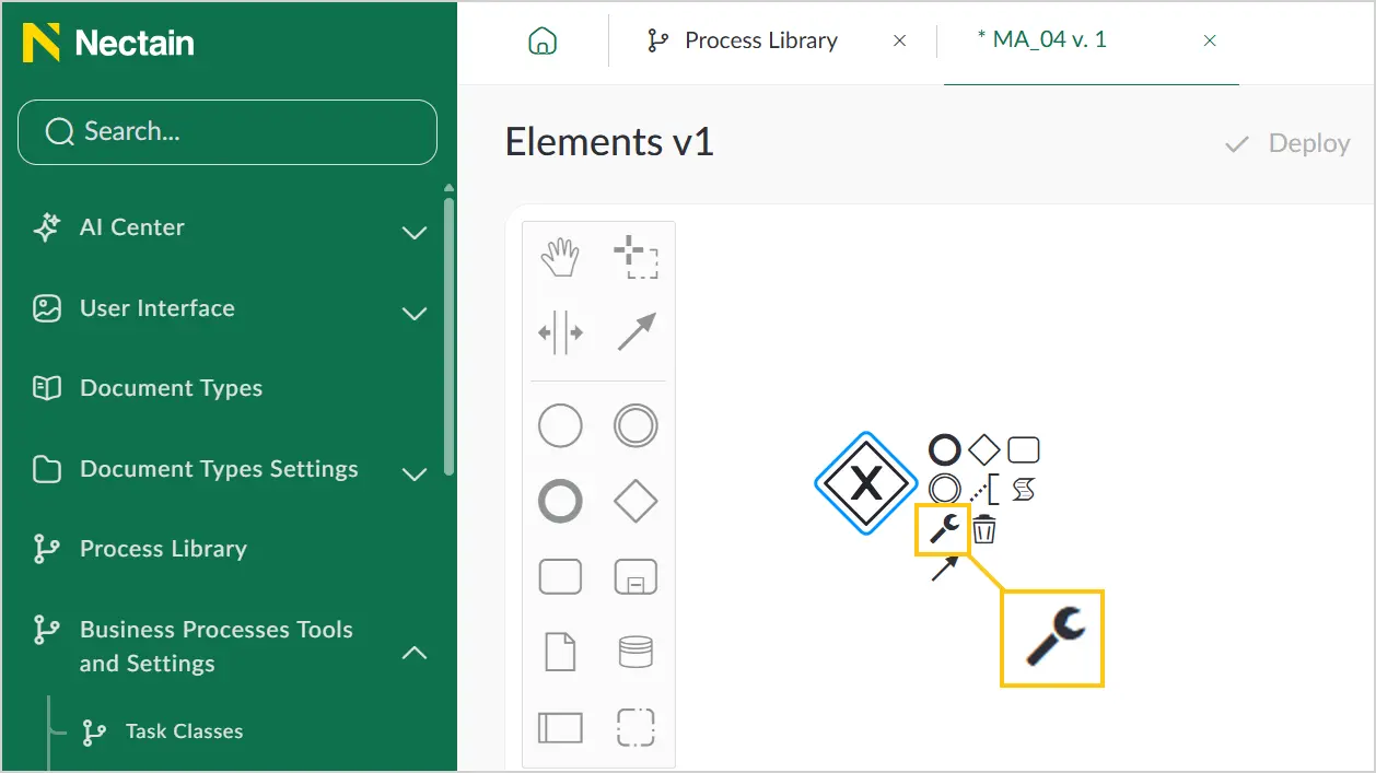
Click on the added gateway, then in the context menu, select the icon.
-
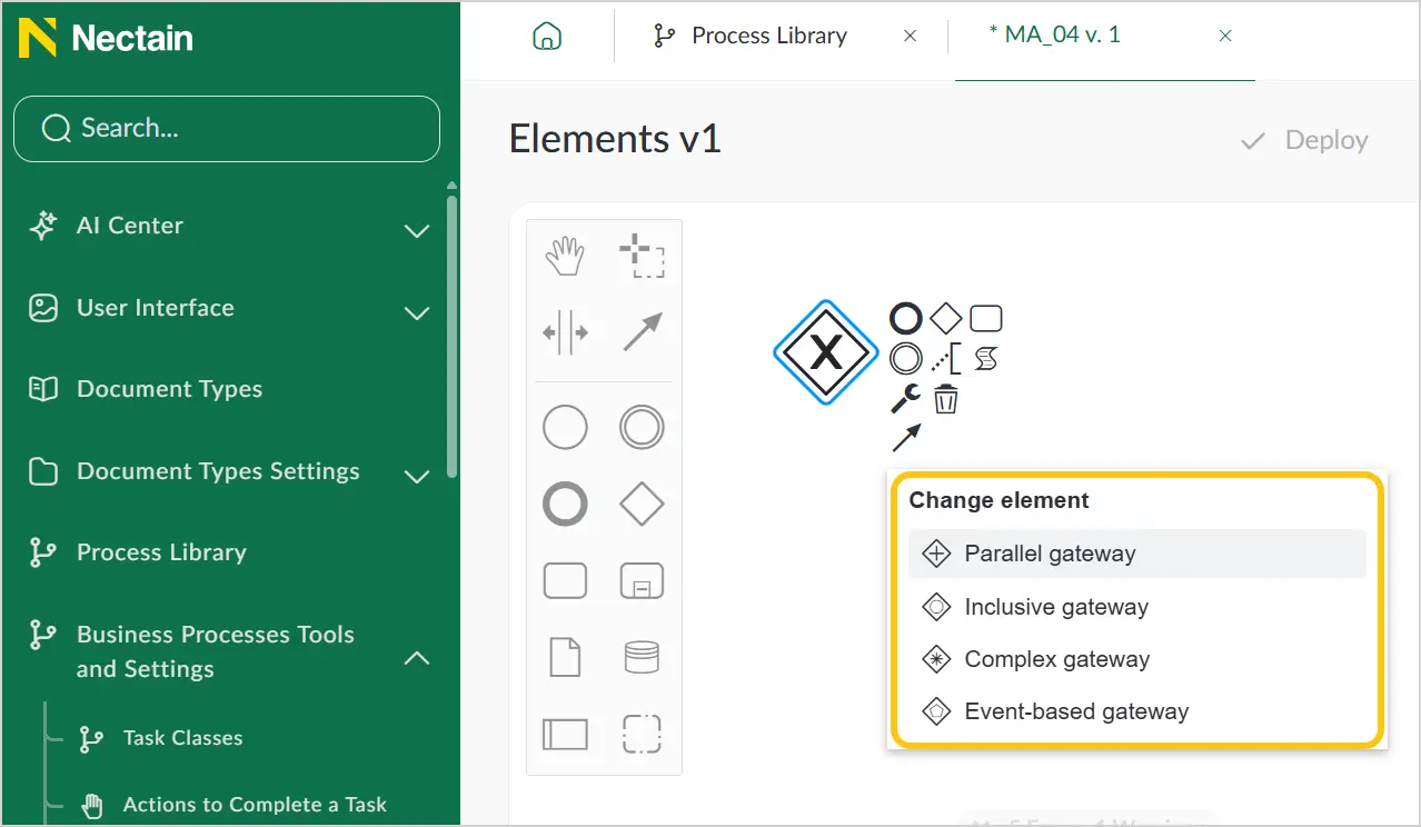
In the context menu, select the required gateway type (see Gateway Types).
2.4.1.4.3. Gateway Types
-
Exclusive OR Gateway, data-driven. When splitting, the gateway activates one of the outgoing flows. When merging — it waits for one incoming flow to complete and activates the outgoing flow.

Example: In a leave request approval process, after the manager reviews the request, an Exclusive OR Gateway is used to check whether the request is approved. If yes, the process moves to approval; if not — it moves to rejection.
-
AND Gateway. When splitting, the gateway activates all outgoing flows. When merging — it waits for all incoming flows to complete and activates the outgoing flow.

Example: In a payroll process, after calculating the salary, the AND Gateway is used to simultaneously send a notification to the employee and the accounting department.
-
Inclusive (OR) Gateway. When splitting, activates one or more outgoing flows. When merging, all activated incoming flows must be completed.

Example: In an order processing process, after order confirmation, the OR Gateway is used to check whether the goods need to be shipped by courier and whether an invoice needs to be sent by email. Both paths can execute simultaneously or separately.
-
Complex Gateway. Models complex branching and merging conditions. Can include logic using multiple conditions and rules.

Example: In a project approval process, after the review stage, a Complex Gateway is used to check whether the project needs to be approved only after receiving comments from both reviewers, or if reviewer "A" has granted special permission.
-
Event-Based Gateway — selects the next flow based on the event that occurred first. Used when the direction of flow depends on an external event. The direction is dictated by which event occurred, not which condition was met.

Example: In a technical support process, after receiving a request, an event-based gateway is used to determine next steps based on whether the customer responded to the request or whether the waiting time has elapsed.
2.4.1.5. Flows
A Flow is a sequence of actions represented by an arrow. The flow element shows the sequence of actions in a business process.

2.4.1.5.1. Add a Flow
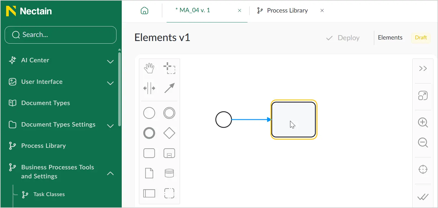
To connect one process element to another, use flows.
To add a flow between two elements:
-
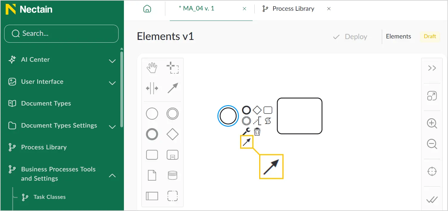
Select one of the added elements, then in the context menu, select the icon.
-
Select the second element to which you want to connect the previous element.
2.4.1.5.2. Change the Flow Type
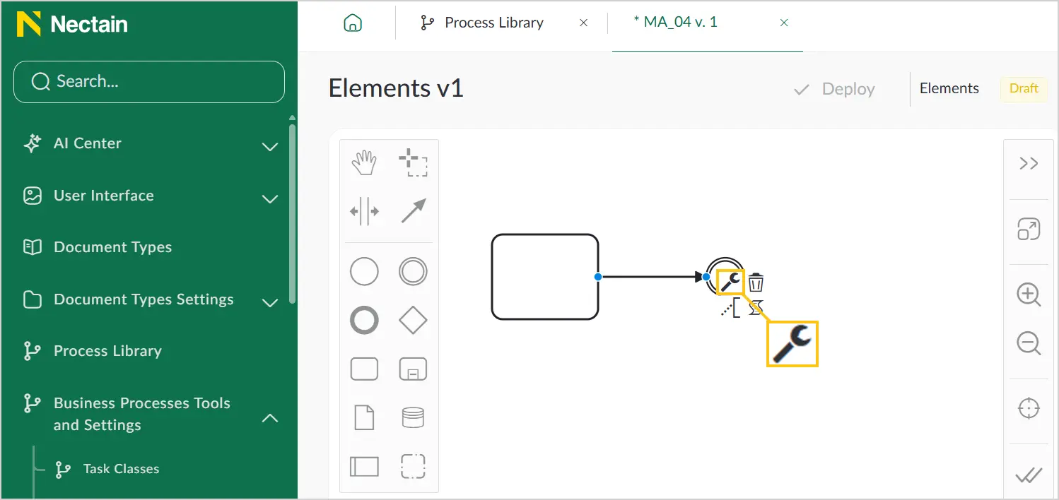
-
Select the added flow, then in the context menu, select the icon.
-
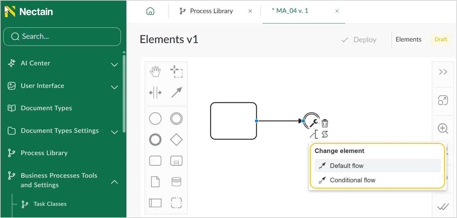
In the context menu, select the required flow type (see Flow Types).
2.4.1.5.3. Flow Types
-
Sequence Flow — the standard flow that does not depend on conditions and does not pass through gateways, meaning it is uncontrolled.
-
Default Flow — use to indicate that the process will continue along this flow only if none of the defined conditions are met.

-
Conditional Flow — use to indicate that the process will follow this flow only if the defined condition is met. If the conditional flow originates from a process, a diamond is added near the base of the arrow. If the conditional flow originates from a gateway, no diamond is added.

2.4.1.6. Artifacts
Artifacts are objects that do not directly affect the execution of a business process. In BPMN, artifacts are used for additional description and supplementation of business processes. They help make models more understandable, detailed, and informative.
The main artifact types in BPMN are:
2.4.1.6.1. Annotations
Used to add comments or additional information to model elements. They help explain or elaborate on certain aspects of the process, providing better clarity for those who analyze or use the model.

2.4.1.6.2. Groups
Used for visual grouping of process model elements to improve organization and clarity. Groups do not affect the process execution sequence.

2.4.1.6.3. Data
Used to represent information that is processed or transmitted within the process. The platform includes the following artifacts of this type:
-
Create a data object reference — use to represent a specific unit of information that is used or created within the process. Data objects can be documents, files, or other types of information objects passed between process stages.
-
Create a data store reference — use to represent a storage location that exists outside the current process but which the process can access to store or retrieve data. This can be a database or a file system.

2.4.2. DMN Notation Overview
DMN (Decision Model and Notation) is one of three standards for modeling aspects of business processes used in the Nectainium platform. DMN is used to create and automate decision-making rules, providing clear and understandable decision logic. See also the detailed DMN definition and the Execute DMN section.
With DMN you can:
- Help all stakeholders understand a complex domain.
- Make decisions using easy-to-read diagrams.
- Reduce the risks of decision automation projects through graphical decomposition of requirements.
- Present simple and accurate definitions of business rules in unambiguous decision tables.
- Simplify the development of decision-making systems using specifications that can be automatically validated and executed.
To configure decision logic, use the Decision Table. A Decision Table is used to represent decision-making rules in a tabular format. It defines which actions are taken based on specific conditions. The table contains sets of input and output parameters and additional attributes that define the rules for working with them.
A Decision Table consists of the following components:
-
Name — identifies the decision table and its purpose.
-
Hit Policy — defines how results are selected when multiple rules can be applied. The main options are:
- Unique — the decision must always produce one unique result (overlaps are not allowed);
- First — applies a single matching rule;
- Collect Sum — applies an aggregated sum.
-
Input expression — the input variables. Their specific values are the input entries.
-
Output expression — for each possible set of input entries, defines the output variable (output entry).
-
Annotations — text used to explain rules. Annotations are not executed.
-
Rules — a set of input and output data that form the table rows. Each rule has a number.

The Decision Table can then be invoked from a BPMN business process — passing input data and receiving output based on the configured conditions. This allows you to significantly simplify the business process diagram by using a DMN reference instead of gateways.